WMS Six Digit Display Set $150 + $5 Shipping
For System 3 - 6.
|
|
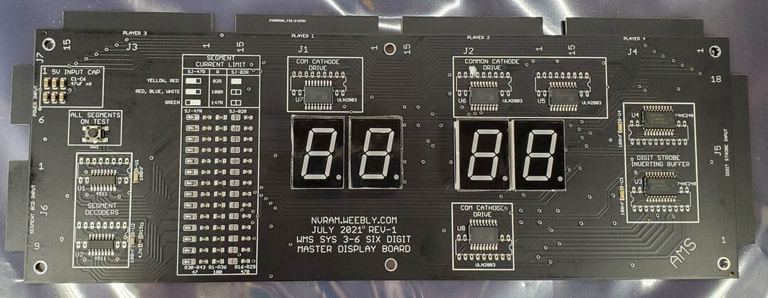
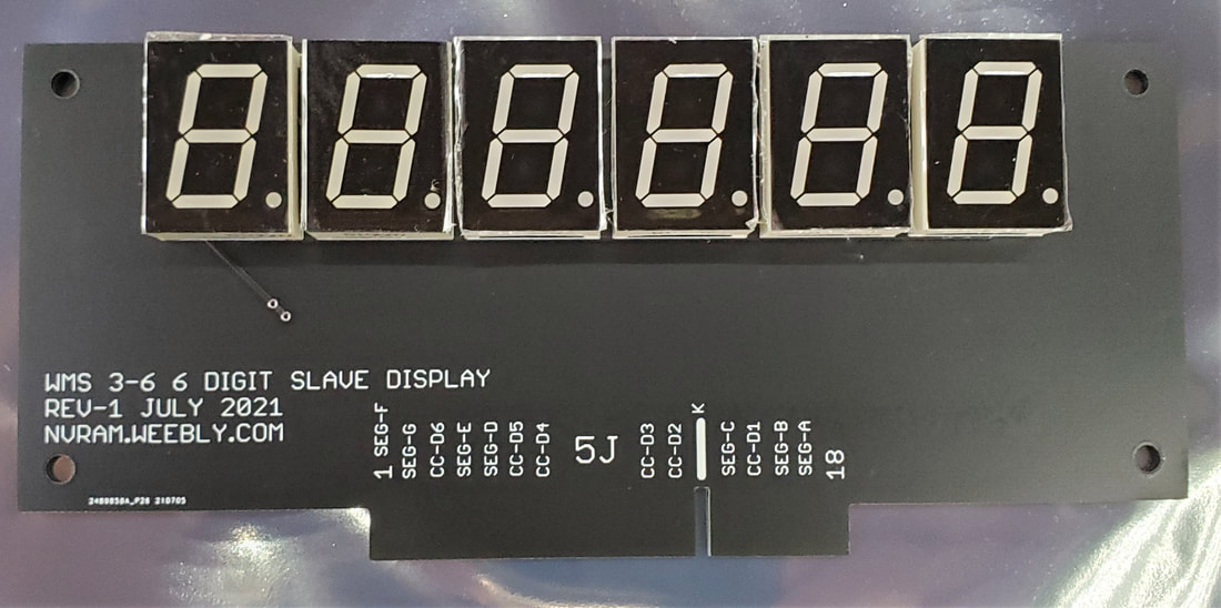
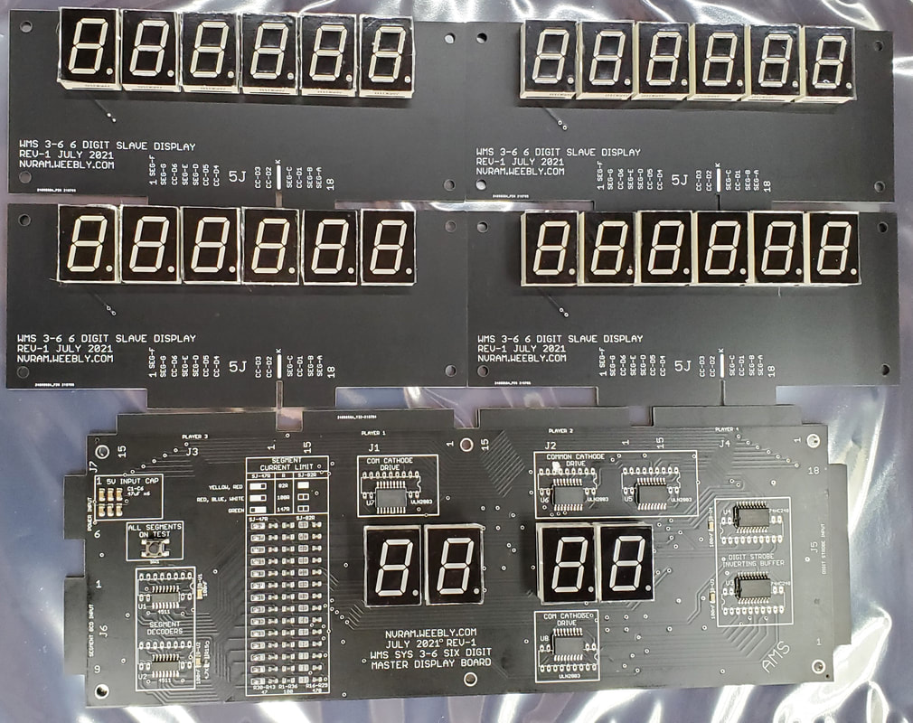
Includes one master display board and four auxiliary displays.
Installation:
Power off game and wait 2 minutes for High Voltage capacitors to discharge.
Remove 1/4A high voltage display fuse from the power supply board.
Remove original displays, leave wiring harness in place.
Install new LED displays using the same mounting hardware and wiring harness.
Peel off and discard protective film from each digit.
Notes and FAQ
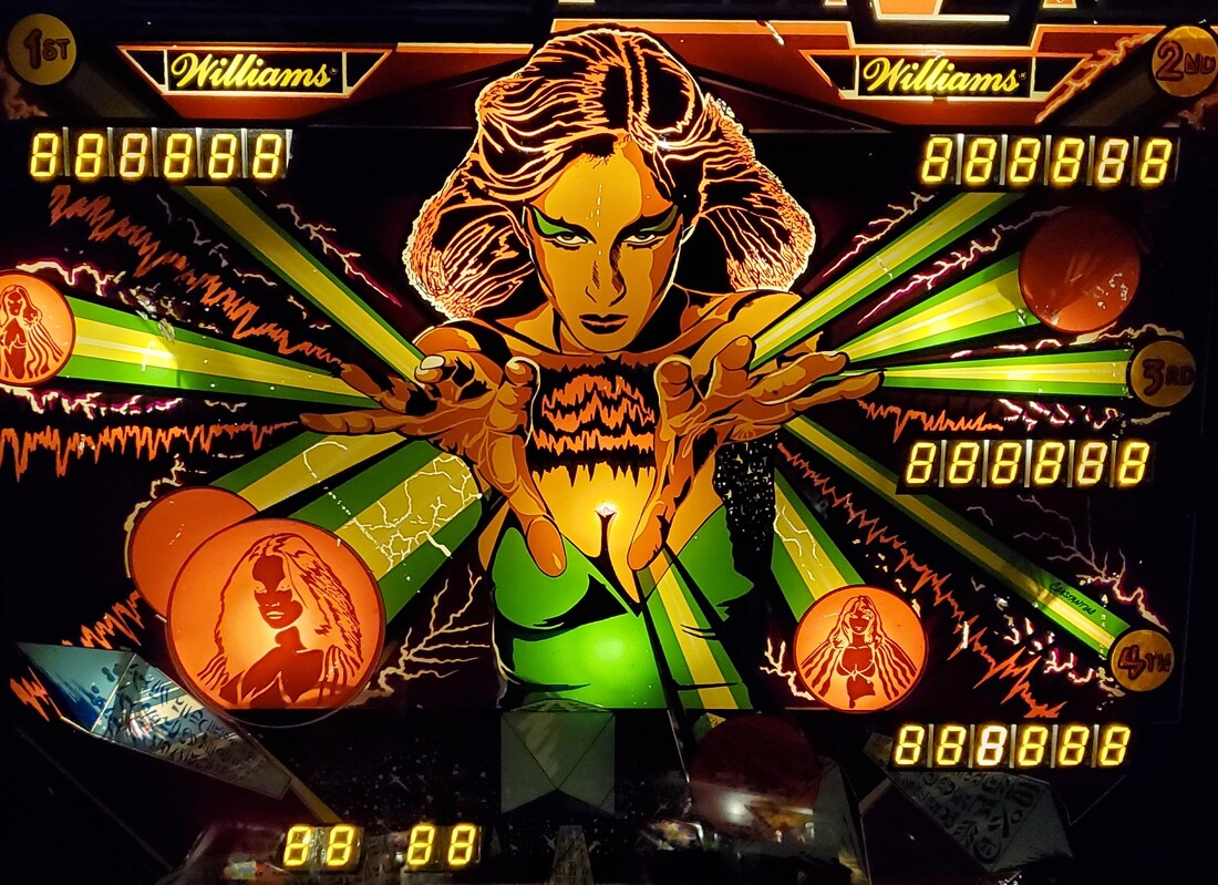
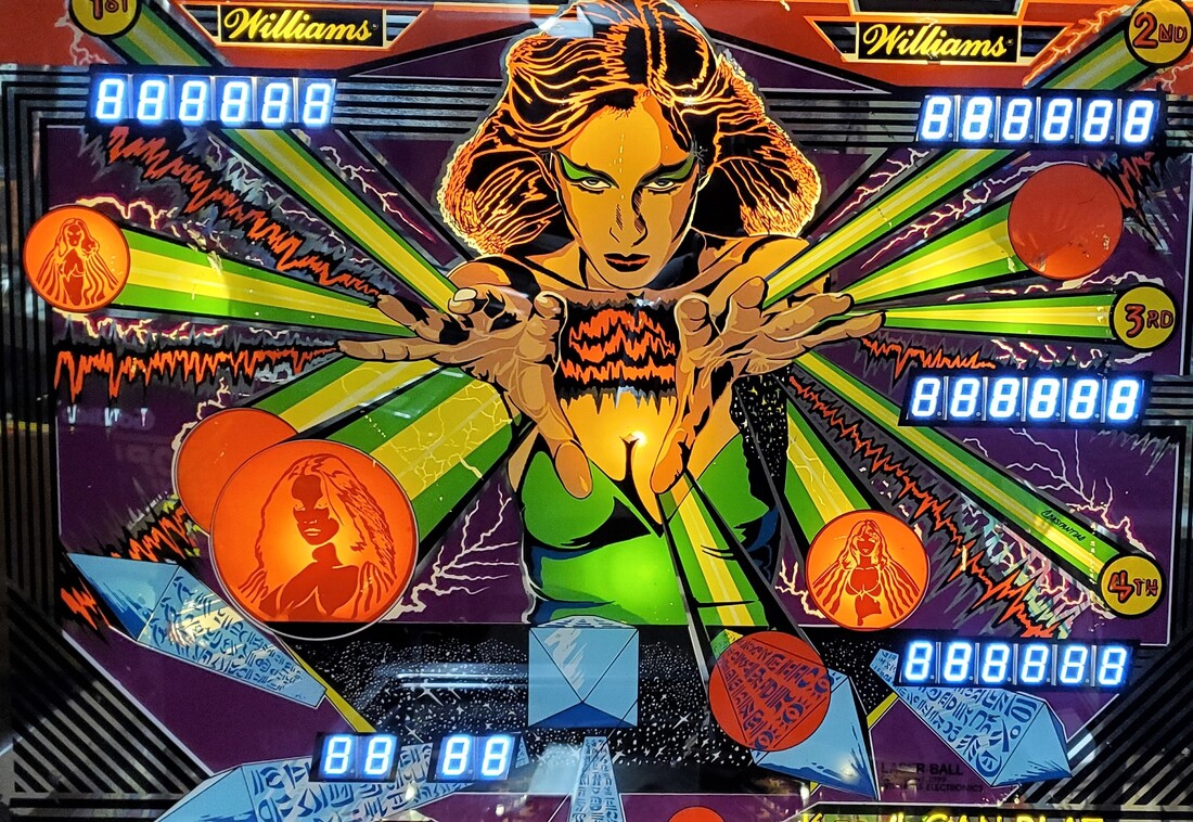
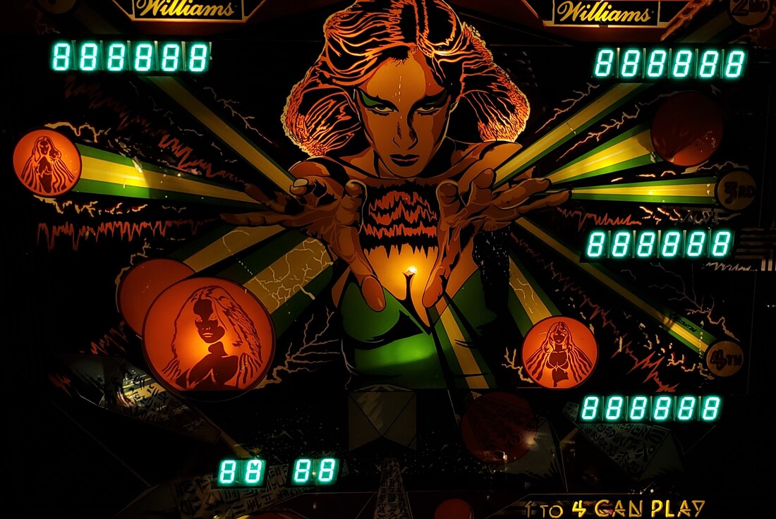
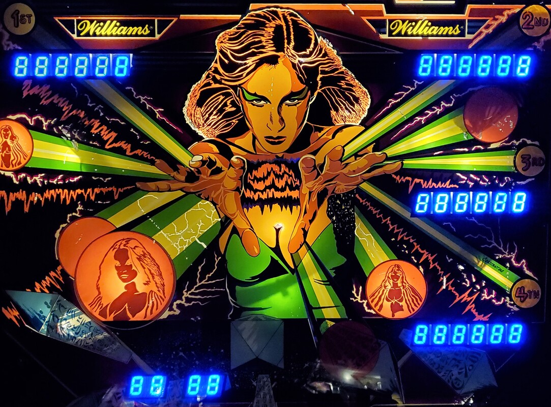
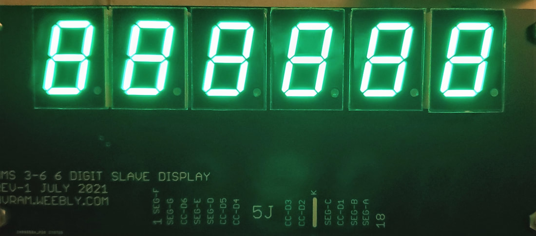
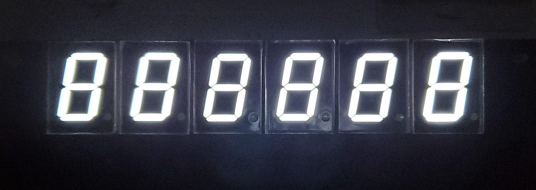
White was hard to photograph without blur in the picture The white digits are well defined in person. Red was hard to photograph the color naturally. The red color is the traditional red LED color. Green color is very vibrant and the color of green is like what is commonly used in multicolor holiday lights.
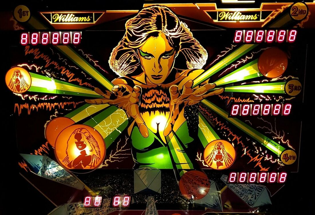
No light blocking foam or covering is included. Light bleed between digits is possible when a GI lamp is close by. This can be seen in the pictures.
Pictures in listing taken while the clear protective film is still in place. Digits have a matte black finish.
Don't scratch your back glass while installing! If the displays are rubbing against the glass or if the displays are out of alignment from back glass windows the backbox lamp/display door is out of alignment. The backbox lamp / display door should visually roughly square to the cabinet head. There are forks on the right side that can adjust how far the display/lamp door closes. The hinge will often be found to loose which lets the door flop around and puts the displays out of alignment.
You cannot mix and match LED and HV plasma displays.
If segments are ghosting when they should be off or if digits are strobing when they should be off likely have an open connector. Display signals come from the connectors across the top of the MPU board and solder joints are frequently cracked there.
If display count is wrong 0, 0, 2, 2, 4, 4 etc. then likely open signal on segment BCD data connector.
Installation:
Power off game and wait 2 minutes for High Voltage capacitors to discharge.
Remove 1/4A high voltage display fuse from the power supply board.
Remove original displays, leave wiring harness in place.
Install new LED displays using the same mounting hardware and wiring harness.
Peel off and discard protective film from each digit.
Notes and FAQ
White was hard to photograph without blur in the picture The white digits are well defined in person. Red was hard to photograph the color naturally. The red color is the traditional red LED color. Green color is very vibrant and the color of green is like what is commonly used in multicolor holiday lights.
No light blocking foam or covering is included. Light bleed between digits is possible when a GI lamp is close by. This can be seen in the pictures.
Pictures in listing taken while the clear protective film is still in place. Digits have a matte black finish.
Don't scratch your back glass while installing! If the displays are rubbing against the glass or if the displays are out of alignment from back glass windows the backbox lamp/display door is out of alignment. The backbox lamp / display door should visually roughly square to the cabinet head. There are forks on the right side that can adjust how far the display/lamp door closes. The hinge will often be found to loose which lets the door flop around and puts the displays out of alignment.
You cannot mix and match LED and HV plasma displays.
If segments are ghosting when they should be off or if digits are strobing when they should be off likely have an open connector. Display signals come from the connectors across the top of the MPU board and solder joints are frequently cracked there.
If display count is wrong 0, 0, 2, 2, 4, 4 etc. then likely open signal on segment BCD data connector.
