BALLY SEVEN DIGIT DISPLAY EXPANSION INFORMATION
Bally / Stern MPU Revision 15 and later supports seven digit displays with some wiring modifications for the following games.
Dolly Parton
Future Spa
Harlem Globetrotters
Kiss
Mystic
Nitro Ground Shaker
Paragon
Playboy
Rolling Stones
Silverball Mania
Space Invaders
Six Million Dollar Man
Viking
Voltan Escapes Cosmic Doom
Because these games use the PIA port that is normally for digit 7 to control the sound board additional hardware and software is required for seven digit displays.
7 DIGIT DISPLAY SETUP INFORMATION
EXTRA ITEMS REQUIRED THAT ARE NOT INCLUDED WITH THE MPU:
22awg wire
Wire insulation. Shrink tubing or equivalent.
Zip wire ties.
1pc - Four pin 0.100" Housing. Molex 22-01-2047 or equivalent.
3pcs - 0.100" crimp pin. Molex 08-52-012 3 or equivalent.
4pcs - 0.156" crimp pin. Molex 08-50-0108 or equivalent. *** If your game is using IDC connectors at the displays you will not need this.
7 digit displays. Plasma or LED will work fine. If using Stern 7 digit plasma display board solder bridge connector pin 11 and pin 12 together.
INSTALLATION
Run a new wire to pin 12 of each display connector. Start at the last display in the wiring harness run and follow it between all seven digit displays (not the credit display). If you have IDC connectors use a punch down tool or a flat blade screw driver and let the wire pass through the connector except for the last display in the wiring harness run. If you have molex connectors preform a double crimp at each display besides the last one in the wiring harness run. Keep the wire long enough past the first display in the wiring harness run to reach the top left corner of the backbox. The green wire in the picture below is the added connections.
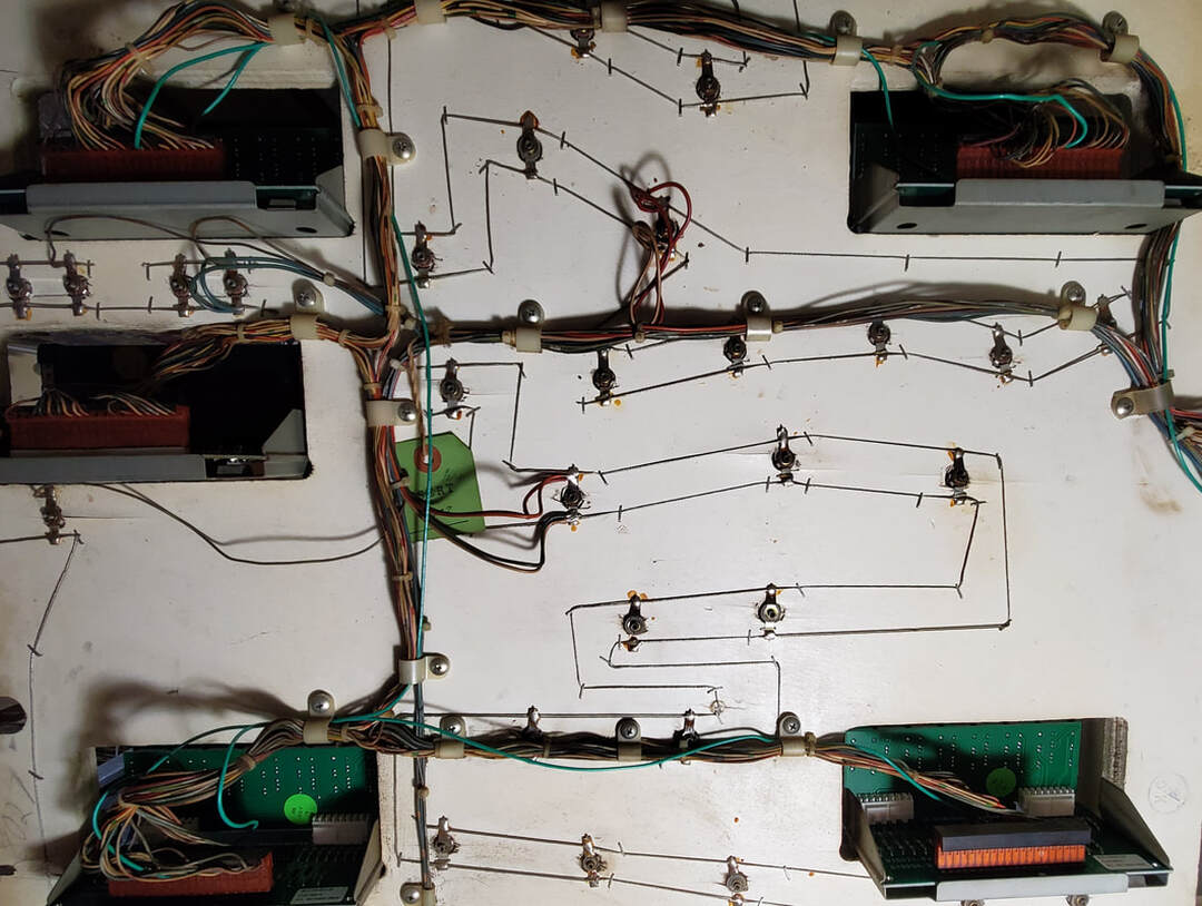
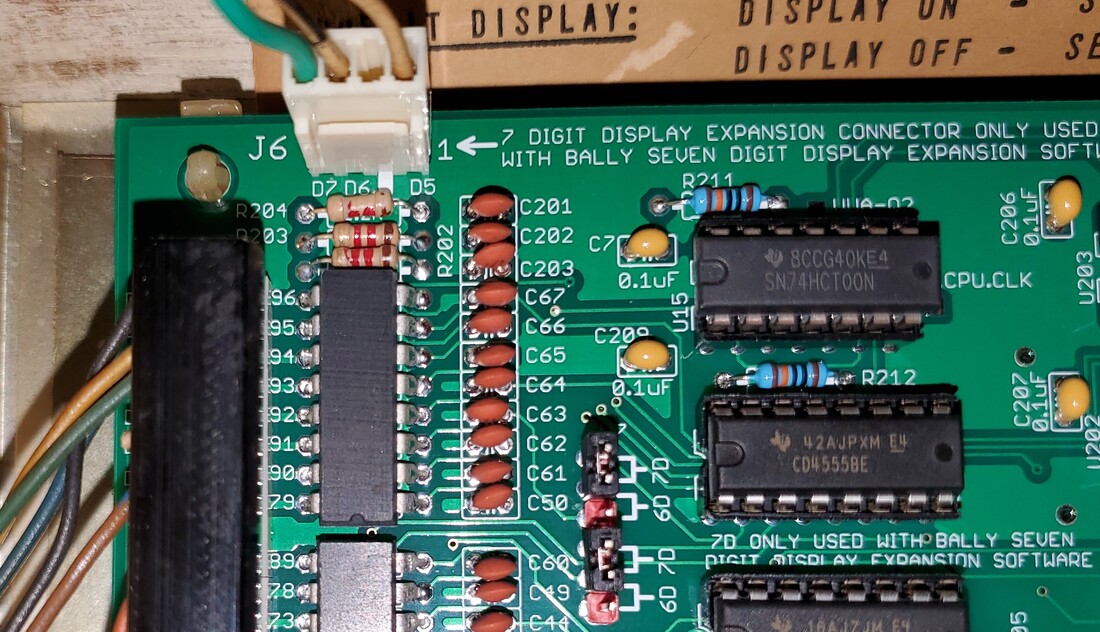
Move MPU J1 Pin 5 to the new added connector MPU J6 Pin 1. This is a typically a white wire with no stripe for digit drive five. You may need to extend the length of this wire if it will not comfortably reach MPU J6.
Move MPU J1 Pin 6 to the new added connector MPU J6 Pin 3, This is typically a white wire with a black stripe for digit drive six. You may need to extend the length of this wire if it will not comfortably reach MPU J6
Connect the wire you ran between pin 12 of each display to MPU J6 Pin 4. This is for digit drive seven.
Move both display count jumpers from 6D to 7D. 7D jumpers is only used for the special 7 digit expansion software, otherwise 6D is always used.
Zip tie and add all the extra wiring to the wire support clips.
Set the game software to the seven digit display version and turn on MPU game option DIP switch 21. See the game selection setup sheet for more information about software.
Install the seven digit displays and you are finished.
Set the game software to the seven digit display version and turn on MPU game option DIP switch 21. See the game selection setup sheet for more information about software.
Install the seven digit displays and you are finished.

Over exposed image to see all digits lit up.
Thank you Oliver Okaegi for the idea and software.
*** Note about Meteor and Embryon Seven Digit *** Wire digit seven of each display to MPU J1 Pin 7.
Thank you Oliver Okaegi for the idea and software.
*** Note about Meteor and Embryon Seven Digit *** Wire digit seven of each display to MPU J1 Pin 7.
